
The Back Half Project
for a 1987 drag race Camaro
Built in a cramped 2 car garage with basic tools. The major work only took a couple of weeks since I've never done a back half project before. A proper chassis shop probably could have done everything in a fraction of the time. It's not a project that would want to do again but after the first one, I have a lot more knowledge on how to do the second one. First time out to the track was a chassis tuning event. The IC and preload were really off. The car launches much better now but the 4.56 gears were just not enough and were replaced with 4.86 to compensate for the taller tires.
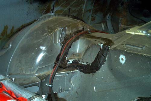
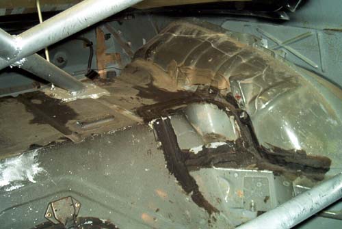
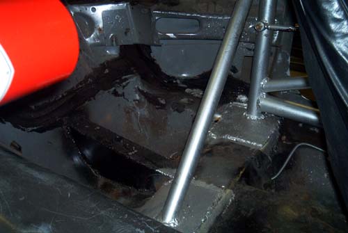
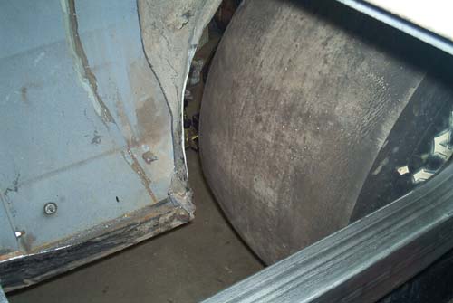
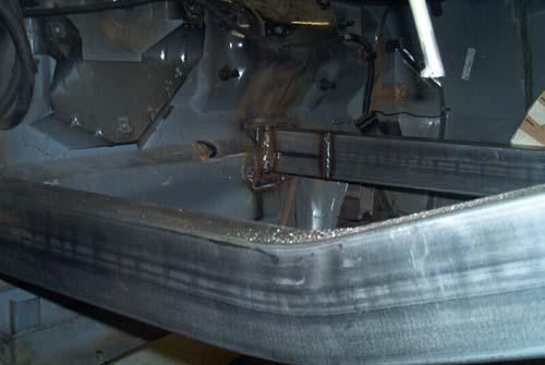
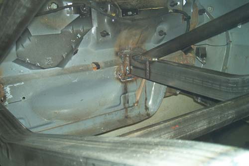
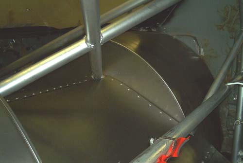
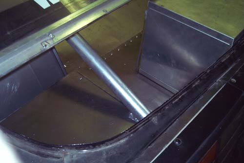
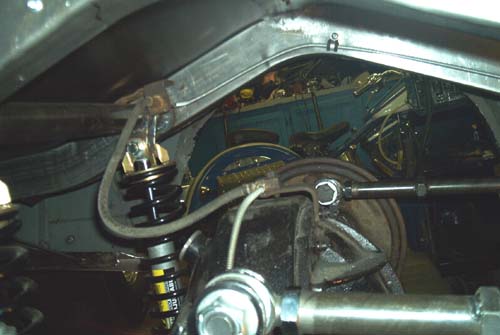
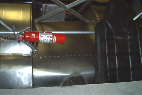
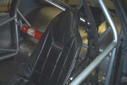
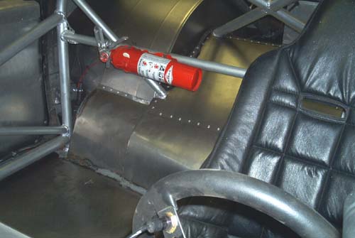
| I finally got around to doing my back half project during Christmas 2006. This isn't a kit because I wanted to do a custom install. These first 3 pictures show the factory rear sheet metal and wheel tubs. You can also see how I originally modified the floor for ladder bars. I finished fabricating a narrowed diff a few months earlier and don't have a photoshoot of it. | |
| All this factory sheet metal is heavier than it looks. The factory uses multiple layers to create a frame and strength. | |
| The square tube running under where the back seat normally sits is for the ladder bars that were under the car. | |
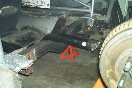
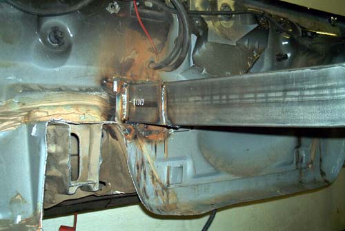
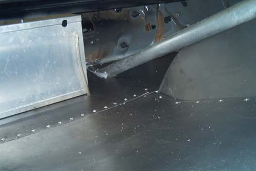
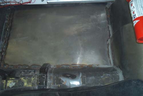
| After cutting out the floor, the front crossmember needed to be installed. This is the hardest part of the whole project since the entire 4-link and back half is based on the position of the crossmember. I spent at least a day doing measurements before finally welding it in. | |
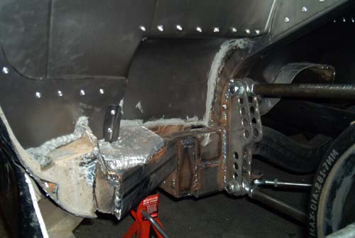
| To keep the 101" wheelbase and the recommended 21" long 4-link bars, the crossmember needed to be positioned farther ahead than what I originally planned. The subframe connectors run under the crossmember and are reinforced at the back and underneath. The crossmember is welded to the inside edge of the outer bracket for the original LCA mounts. It was easier than cutting it all out and plating a mount on the rocker panel. The LCA mount is thick steel and very strong. Once the 4-link project was finished and I started playing with IC points, I found the crossmember could have been installed a couple of inches lower. Probably more inline with the subframe connectors. | |
| After a lot of measuring, using a level and plumb bob to find centerlines, the frame rails were trimmed to length then welded in. | |
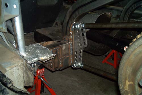
| I wanted the front brackets lower than what would be considered normal looking. The goal is to have the bottom mount hole 6-8" from the ground. To do this I needed to run the brackets below the crossmember. An extra piece of crossmember was welded underneath to provide extra support. The front mount brackets were then welded on and all the bars installed. The diagonal link was replaced shortly after the install with a wishbone system. If I had installed the crossmember lower, the extensions wouldn't be needed. | |
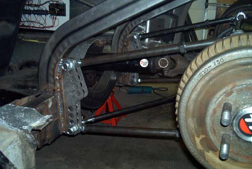
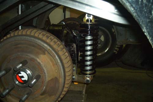
| The shocks are mounted. Nothing fancy here. Position an upper mount in the rough position, make sure it's square and level then weld it in. | |
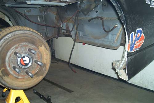
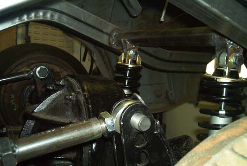
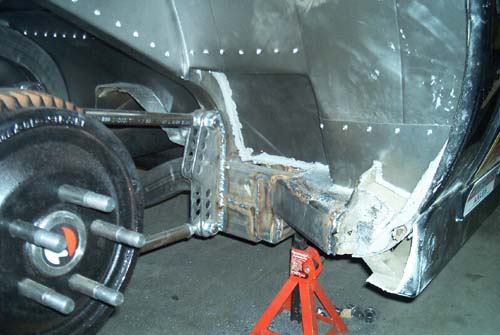
| Final ride height adjustment will need to be made once everything is done. Those are 5/8" wheel studs and Ford drum brakes. | |
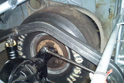
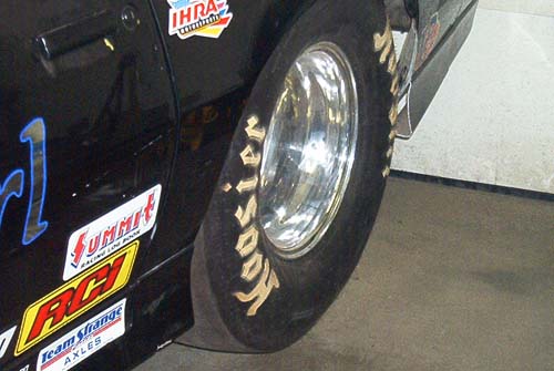
| I mounted a tire to check clearances before I started building the wheel tubs. The diff was jacked up until the suspension started to lift the car. The back of the fender opening had already been trimmed from the previous wheel/tire combination so it's not as tight as a stock fender opening would be. I think I may extend the wheelbase slightly to help improve the front gap. I'm currently checking to see how much tire growth I can expect. I got a reply back on tire clearance. I need about 1-1/2" from the front and rear fender lips to allow for any tire growth. | |
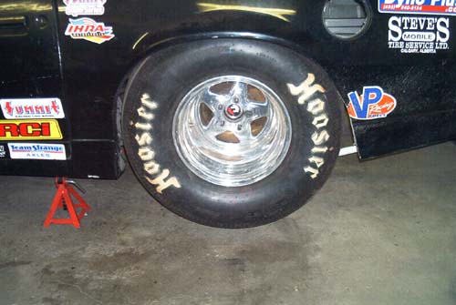
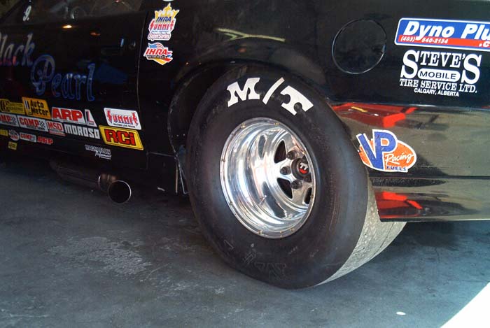
| When the new MT tires were installed and I got some track time, I never had any rubbing on the tires. These Hoosier tires are old, worn out spares that I'm only using for fitments. In the spring, I'll have new MT 32x14 slicks mounted. The rims have 5.5" of backspace and are 15" wide. | |
| My diff measurements came out pretty good but I could have gotten the rims with 6.5" backspace to tuck the tires under a little more. There's about 3" between the tire and the 26" wide frame rails. | |
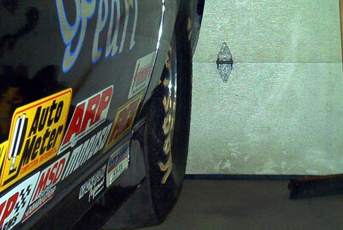
| An angled look along the side of the car shows how far the wheels are tucked under the fenders. | |
| There is more tire under the fenders than when I had my old tires. | |
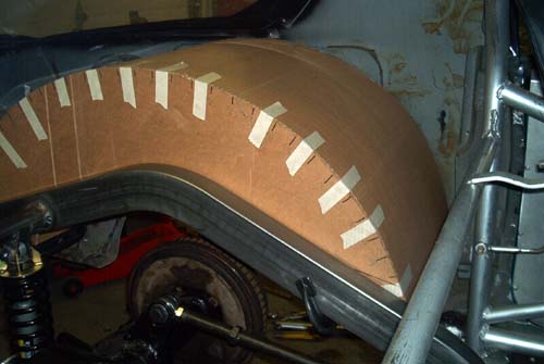
| The cardboard mock up tub. Nothing fancy. Following instructions, you make a rough estimate of how it's to fit. You then transfer the inner fender outline to the cardboard then transfer that outline to the metal tub to be cut for an almost perfect fit. | |
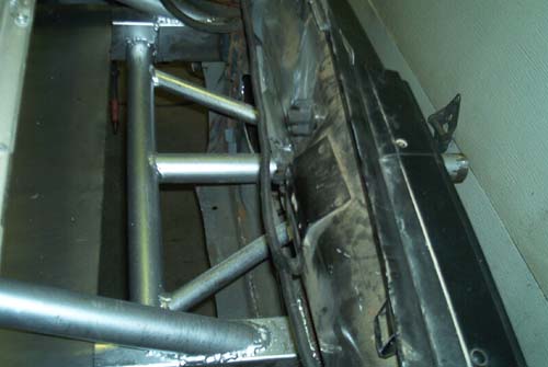
| The rear frame rail mounts didn't turn out exactly the way I wanted. The plates were welded to the rear of the car. AFTER both frame rails were welded to the plates I discovered my rear centerline was off. There was no way I could cut the rails right at the plates so I just cut them back about 6 inches, repositioned them off the proper centerline then welded a section back in. I would have liked to have them lower, more inline with the bumper height but they're not weight supporting at the rear. | |
| They hold the rear sheetmetal up. The roll cage tubes (still to go in) support the frame rails. The driver side tub is finished but the tubs will go in last to allow room to install the tin between the frame rails. I still need to make the passenger side tub. | |
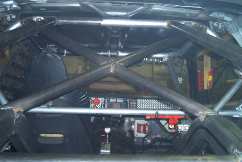
| All the rear roll cage tubes are in. These pics are before I painted the tubes. All the required welding for the project isn't finished but it's getting closer. | |
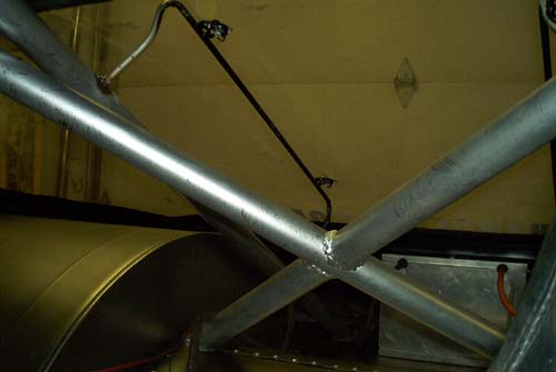
| Lots of extra braces. | |
| Without braces, 4-link frame rails would have no support. | |
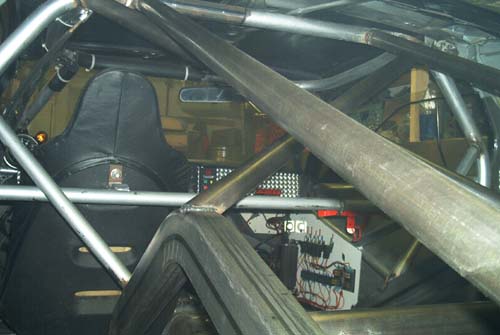
| One last pic showing the the rear tubes right at the rear of the frame rails. I was considering installing a battery tray between the frame rails but decided to make a parachute mount in there instead even though I don't need it yet. The battery tray will mount off the outside of the passenger frame rail. | |
| Here's the parachute mount. I need the clevis for the end to make it complete plus a support to hold the chute. I'm a long way from needing a chute but it wasn't hard to install the mount at this time. The floor tin will go across the top of the frame rails and with some battery supports under the tin, the battery box will be mounted on top of the floor in the center. | |
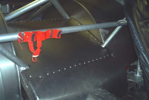
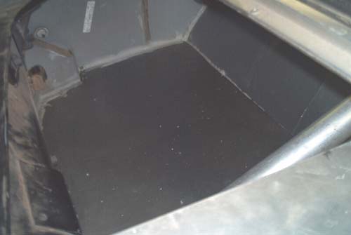
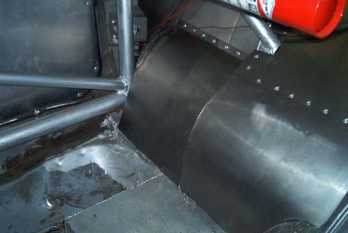
| The main part of the tin work is done and the tubs are in. The front and rear part of the tubs still need to be sealed off. That's going to require more tin work. | |
| Don't expect to have a back seat in a third gen with a 4-link. | |
| It looks pretty but won't win any car shows. | |
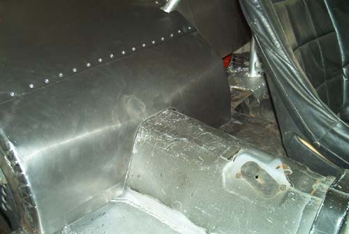
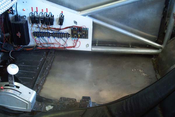
| Finally finished the tin work behind the tubs. Under the battery box between the frame rails is some 1" angle iron that supports the battery box. The battery still needs to be installed and cables routed. All the tin has been sealed with caulking. The tin work at the front of the tubs is going to be a little more difficult because of the multiple angles and the required access to the front 4-link mounts for adjustments. I'm still pondering the best course of action for this. In the first pic, you can see the aluminum channel I use to hold the Lexan rear window. Yes I'm doing this back half with the window still attached to the car. It's actually a lot of work to remove it. | |
| The rear section was done in 3 pieces to make installation easier. | |
| Sealed everything up with a caulking after a lot of trimming to make it fit. | |
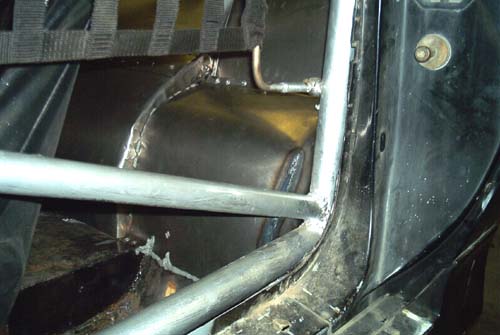
| This picture shows the backside of the tin work at the front of the tubs. You need to have enough room to access the front links for adjustment. Because the crossmember is forward to my main hoop, I wanted more bracing for the plate that the hoop is welded to. This became a simple fix by welding a piece of crossmember tubing from the crossmember to the rocker panel then welding the plate to the brace. Unless I go with some stupidly tall tires, there will never be a clearance problem. You can also see how much I trimmed off the front of the wheel openings to allow the taller tires. | |
| All the seams have been filled with a caulking. One, to seal up the gaps between the tin and two, to help hold the tin in place. Unless it's all welded up solid, there's only so many places that it can be attached with pop rivets. This isn't a show car. Just make it functional. | |
| Here's what the front tin looks like from the top. I had all week to decide the best way to do this. Finally I decided to make a rounded 3 sided box. | |
| Typically, the roll cage main hoop is forward or on the crossmember and these front pieces go right out to the quarter panels. | |
| That's about it. I'm going to redo the floor sections under where the front seats normally sit to join the floor up to the front tin work. I need to bleed the brakes. I also need to secure the wiring that runs to the back for the battery and lights but other than that, the majority of the work is now done. Just some fine tuning and cleanup work. That only took a couple of weeks not counting narrowing a diff. | |
| Once I get the car back on the ground, (needs front spindles first), I can take some measurements for all the 4-link holes to do calculations to find the IC points. Right now the top bars are in both top holes and the bottom bars are in both bottom holes. | |
| I finished putting the rear window supports back in but the welds still need to be painted. | |
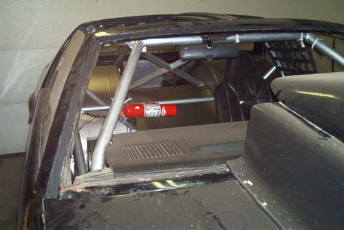
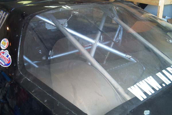
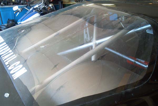
| The windshield is out and being replaced with Lexan. Here's a bunch of pics looking in through the windshield. | |
| With the T-tops out, you can see the halo bar of the cage. | |
| Again, nothing pretty. | |
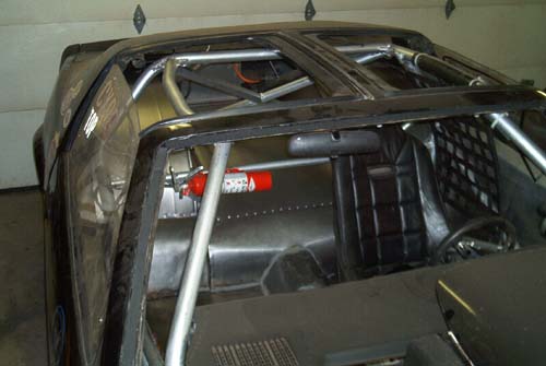
| Pics looking in through the door | |
| Lots more caulking to seal the floor. | |
| A shot of what the passenger side floor now looks like. I never did modify the driver side. | |
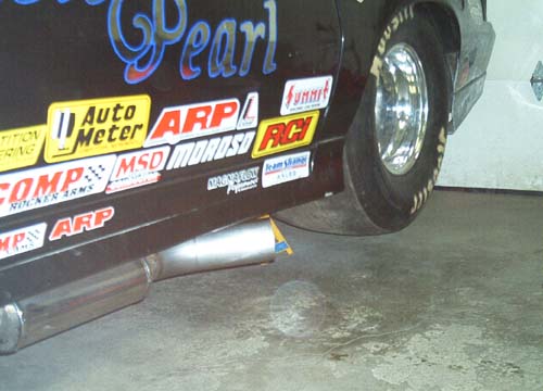
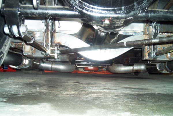
| Here's what the exhaust turnouts now look like. 4" outlets coming out just below the rockers. The passenger side looks the same but there's isn't enough room for me to get a good picture of the side. | |
| The tire is sitting too high up in the body. Once the car was on the ground, the ride height was readjusted. | |
| The car is finally sitting on the ground. You are looking in through the back window. There a bit of glare off the Lexan but you at least see the tin work. | |
| Notice the pop rivits around the outside holding the Lexan in. The Lexan is under the body skin. The entire seal lip has been cut out to do this. No air can get under the Lexan going down the track. | |
| The camera almost sitting on the floor at the rear looking forward. There's a flash glare off the crossmember that I can't edit out. | |
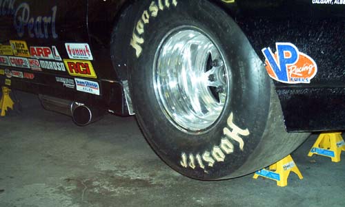
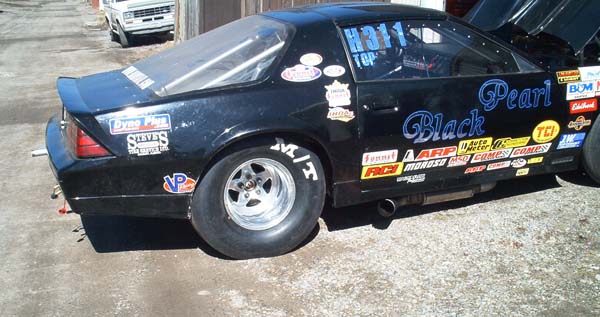
| OK, Now this doesn't look great but should still work. I only took pictures of the passenger side tire because the driver's side would have been in shadow. The driver side wheel opening looks much better than the passenger side. The factory body is not symmetrical from side to side. | |
| Although the opening looks tight, it's an illusion. The tire is actually inside the rear part of the opening. The ground effects make it look like the tire is closer to the fender than it really is. There's actually 1 to 1-1/2" between the tire and the closest piece of fender. Behind the ground effects, the metal part of the fender has been trimmed back. A wheel opening that's been properly opened up would look better. That requires more sheet metal work than I want to tackle. | |
| This is just another shot of the passenger floor. | |
| This pic is looking at the driver side tire. Best angle I can get right now. See the next pic for how much junk is in my garage. I now have the ride height adjusted about to where I started from. The distance from the floor to the bottom of the ground effects directly under the rear corner of the door is just under 10". |
 |
| This is from a low angle at the rear. My garage is much higher than the alley and I'm crouched down slightly. Even though there's a slope to get into the alley, my exhaust doesn't scrape but it's very close. | 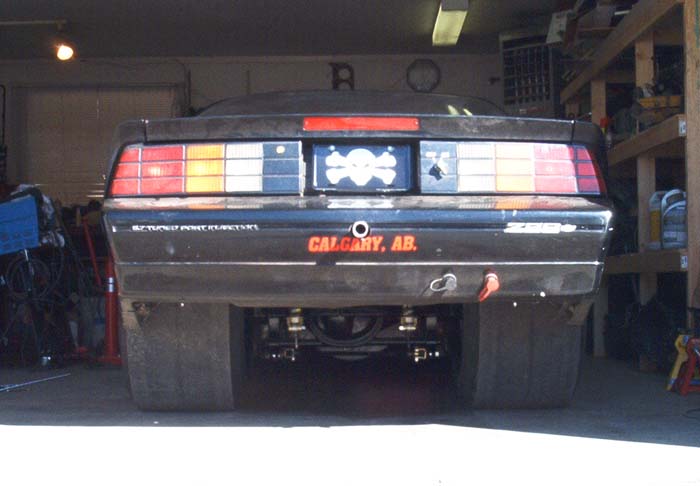 |
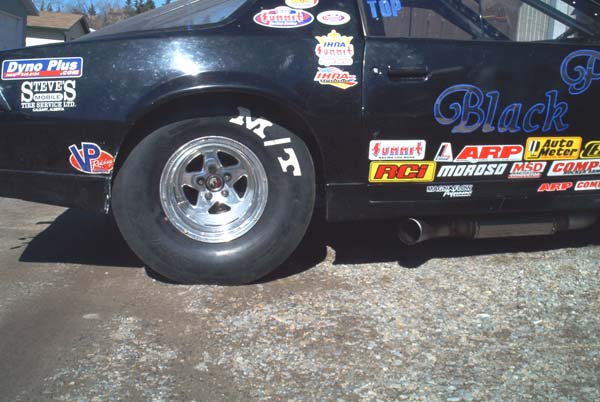
| Passenger side rear of the wheel openeing. I trimmed it back a little more after this pic. After a few passes down the track, this is where I expected to see any rubbing and there was none. | 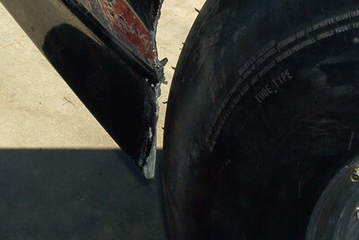 |
| These pictures show how much wheel opening is at the top. Not sure how good this angle will show it but it's the best I can do. | 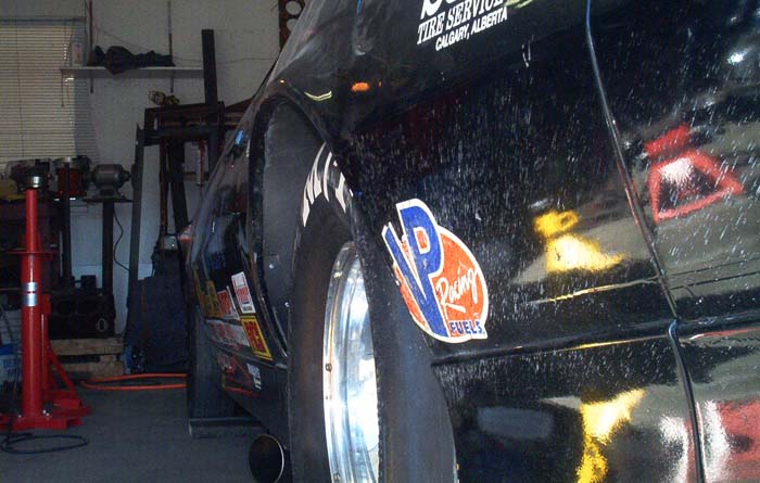 |
| Because the body isn't the same from side to side, there's actually more room at the top on the passenger side. | 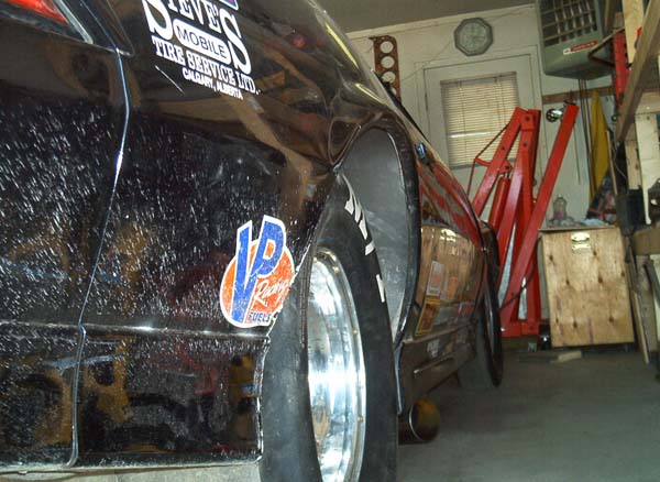 |
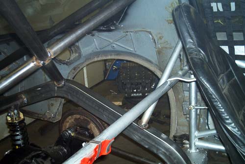
| This picture shows how much clearance there is on the inside rear of the passenger tire. You can also see the brace I installed for fender support. | 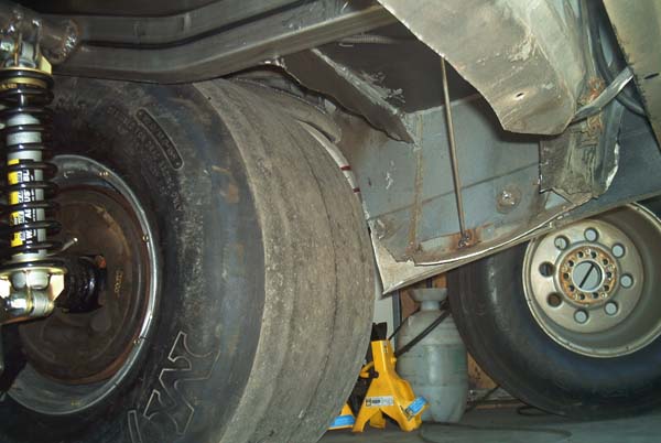 |
A pic showing ground clearance. The camera is sitting right on the floor. 4" exhaust outlets. On the right side of the picture you can see my SFC welded to the underside of 4-link crossmember. |
|
| Last pic just showing the rear. You can see the pipe coming out the back for a future parachute mount. I don't need it yet but during construction, it didn't take much to add it in. The battery master switch mounted to the right of the license plate. Skull and crossbones license plate to match the car theme. Boost posts to easily boost the battery without having to take the deck lid and battery box top off. The factory lettering on the left side still says "5.7L Tuned Port Injection". On the underside of the bumper cover you can just barely see the air ports when I ran air bags in the springs years ago. I just never took them out of the cover. And that's it. | 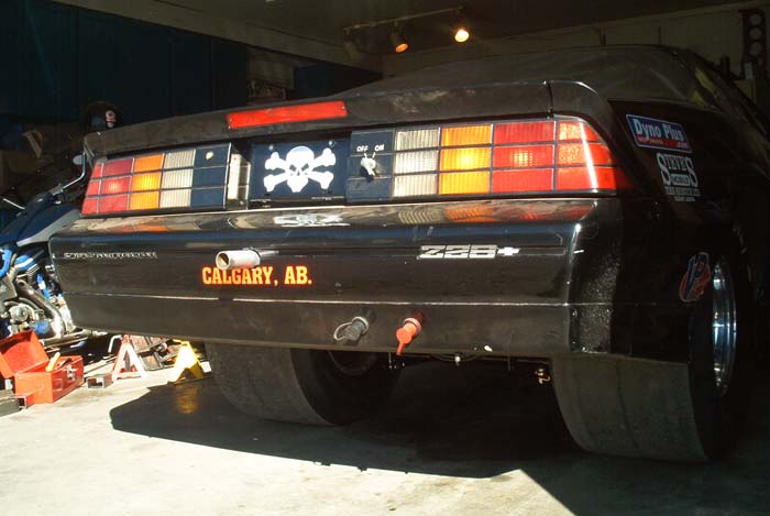 |